Trending Now
 India launched Bharat Taxi Service as First Cooperative-Owned Digital Mobility Platform
 India places World’s First Live Commercial Order for Hyperloop-Based Cargo Logistics
 How Weigh-in-Motion Systems Are Revolutionizing Freight Safety
 Women Powering India’s Electric Mobility Revolution
 Rail Chamber Launched to Strengthen India’s Global Railway Leadership
 Wage and Hour Enforcement Under the Massachusetts Wage Act and Connecticut Labor Standards
 MRT‑7: Manila’s Northern Metro Lifeline on the Horizon
 Delhi unveils ambitious Urban Mobility Vision: Luxury Metro Coaches, New Tunnels and Pod Taxi
 Qatar approves Saudi Rail Link Agreement, Accelerating Gulf Railway Vision 2030
 UP Govt plans to introduce Water Metro services in Ayodhya, Varanasi & Prayagraj
Know standard specifications of proposed MetroNeo Light Rail System in India
Anushka Khare
Posted on: 2020-11-06 13:05:00
Viewer: 10,488
Comments: 0
Country: India
City: New Delhi
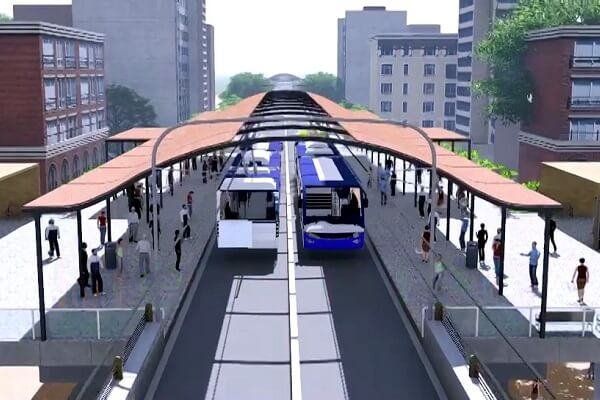
The Ministry of Housing & Urban Affairs (MoHUA), Govt of India on 5th November 2020 has issued Standard Specifications for MetroNeo suited for Tier-2 cities or outer areas of Tier-1/ megacities with projected Per Hour Per Direction Traffic (PHPDT) for next two decades up to 10,000 today.
Salient features
- Elevated or At-grade shared Right of Way (RoW)
- Rubber-tyred bi-articulated electric coaches – quality at par with Metro
- Overhead traction of 750VDC
- Coaches are capable of running on battery in Non-OHE zones.
- Guided coaches for passenger safety and also upgradable to LRT
- Small stations – Entry from footpath to platform through lift/link bridge
- Higher acceleration and deceleration
- Coaches can run very close to each other thus attaining lesser headway
- Telecom network to connect coaches, provide ticketing and smart passenger information system.
- Superior in terms of vibration, noise, acceleration and cost
Civil Parametres for Elevated MetroNeo
- Width of viaduct = 8m
- Shared right of way can be planned for 8m of the viaduct
- Road space occupied for piers is max 2.2m
- No Concourse level in elevated stations, All technical rooms and TOM planned on Platform level only.
- Platform width for the elevated station is 2.25m on either side, length of the platform is minimum 30m
- Foot over bridges and elevators are planned for entry/exits.
- Turnarounds are provided at terminals of the corridor.
- Vertical gradient for viaduct = 5%
- Desirable horizontal turning radius = 90m
Civil Parametres for At Grade MetroNeo
- Shared RoW for Metro Neo. If dedicated RoW is to be provided then continuous fencing/plinth is provided
- Width occupied 8m (RoW) on the roads (for UP+DN line) and 12m at the stations.
- If road width is not available, a Single line (4m) shall run on one road and the other line is planned on the parallel road.
- Width of each platform = 2.25m, length of the platform is min 30m
- Station roof shall be optimized up to the platform area, not the entire road width
- Ring network to be planned to reduce the headway.
- Crash barriers are provided for collision prevention
System Parameters
Rolling Stock
- Rubber-tyred electric coaches with Axle load 10-12Ton
- Coach width = 2.55m
- 2 types of coaches single articulated with 18m length and double articulated with 25m length
- 18m coaches have passenger capacity = 140 and 25m coaches have 250
- Car structure shall be stainless steel or Aluminum
- Sufficient Battery capacity up to 20-25KM at non-OHE zones
- Max operating speed = 65kmph
- Average speed = 30kmph
- Front or Back or Side evacuation can be possible as per Metro authority
- Anti-collision devices in coaches to prevent forward collision and Overspeed warnings ROLLING STOCK
- Operate on 750 VDC Overhead traction (parallel overhead wires)
- Dedicated HT supply (22/33 kV) will be availed from Grid substation thereby avoiding the requirement of Receiving Substation (RSS).
- Ring Main Network - The power supply at 22/33 kV voltage level will be distributed along the alignment through 33kV Ring main cable network for feeding Traction Substations (TSS).
- These cables will be laid in dedicated ducts along/below the viaduct.
- A Traction substation (TSS) for every 2-3 km will be envisaged
- The contact wire shall be hard-drawn copper or copper alloy wire, usually with a cross-section ranges from 80/100/107/120/150 mm2
- Height used for standard contact lines - 5.5m and for lines under bridges or for depots - 4,5m up to 5,5m.
- Catenary switches are provided on OHE wires for route diversions
Traction & Power Supply
- Operate on 750 VDC Overhead traction (parallel overhead wires)
- Dedicated HT supply (22/33 kV) will be availed from Grid substation thereby avoiding the requirement of Receiving Substation (RSS).
- Ring Main Network - The power supply at 22/33 kV voltage level will be distributed along the alignment through 33kV Ring main cable network for feeding Traction Substations (TSS).
- These cables will be laid in dedicated ducts along/below the viaduct.
- A Traction substation (TSS) for every 2-3 km will be envisaged
- The contact wire shall be hard-drawn copper or copper alloy wire, usually with a cross-section ranges from 80/100/107/120/150 mm2
- Height used for standard contact lines - 5.5m and for lines under bridges or for depots - 4,5m up to 5,5m.
- Catenary switches are provided on OHE wires for route diversions
Signal, Telecom and AFC
- Line of sight Signalling dependent on the driver with anti-collision devices and speed limits
- The central monitoring system of coaches in the control centre with GPS based system
- Fiber optic cables, minimum CCV surveillance in stations, an intelligent display system for coach arrival departure.
- Centralized storage is given and telecom racks can be placed below platforms avoiding separate telecom rooms.
- Ticket validators are installed inside coaches with NCMC ticketing systems
- Tickets are available at stations, TVM’s in local shops and other landmark areas in the city
- No AFC gates in stations
Guidance System
- Kerb guidance system can be used in Metro Neo
- Small guide wheels are attached to the bus axle and are guided by vertical curves on either side of the lane.
- These guide wheels push the steering mechanism of the bus to keep it on centralized path. The bus can be steered in a normal way if it is away from the guideway.
- This system permits high-speed operation and precise positioning.
- This type of guidance system is relatively inexpensive as compared to other systems.
Maintenance Depots
- Entry/Exit shall be toll plaza type with inlet points
- The maintenance and stabling or more facilities for coaches can be done in one depot
- Depot to be planned without OHE except for OHE maintenance shed
- Coaches are to be operated on battery at depots
